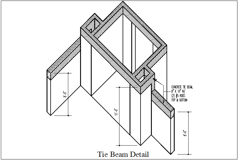
Tie Beam Roof Section Design AutoCAD Drawing Cadbull
A tie beam is a structural beam that connects two columns at any height higher than the floor. The term "tie", which refers to its purpose, is used to connect two columns or other structures. Tie beams can be used to reduce the effective length of columns and to decrease their slenderness ratio. Primary and secondary beams have different tie beams.

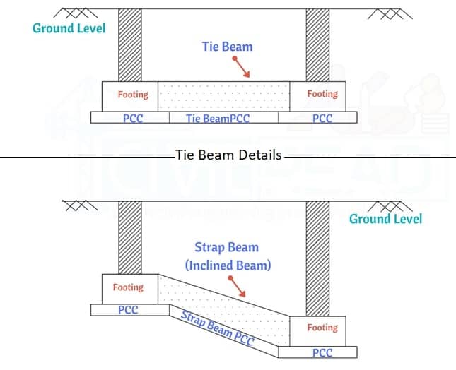
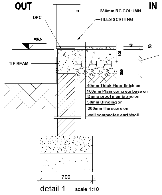
Firm work details of lower tie beam or footing tie beam or foundation
Tie Beam Details These types of beams are used in buildings where the roof or slab height is greater than the structure's normal height. In the columns, tie beams serve as a height breaker. The Tie Beam joins two or more columns together to maximize their effective length and slenderness ratio.
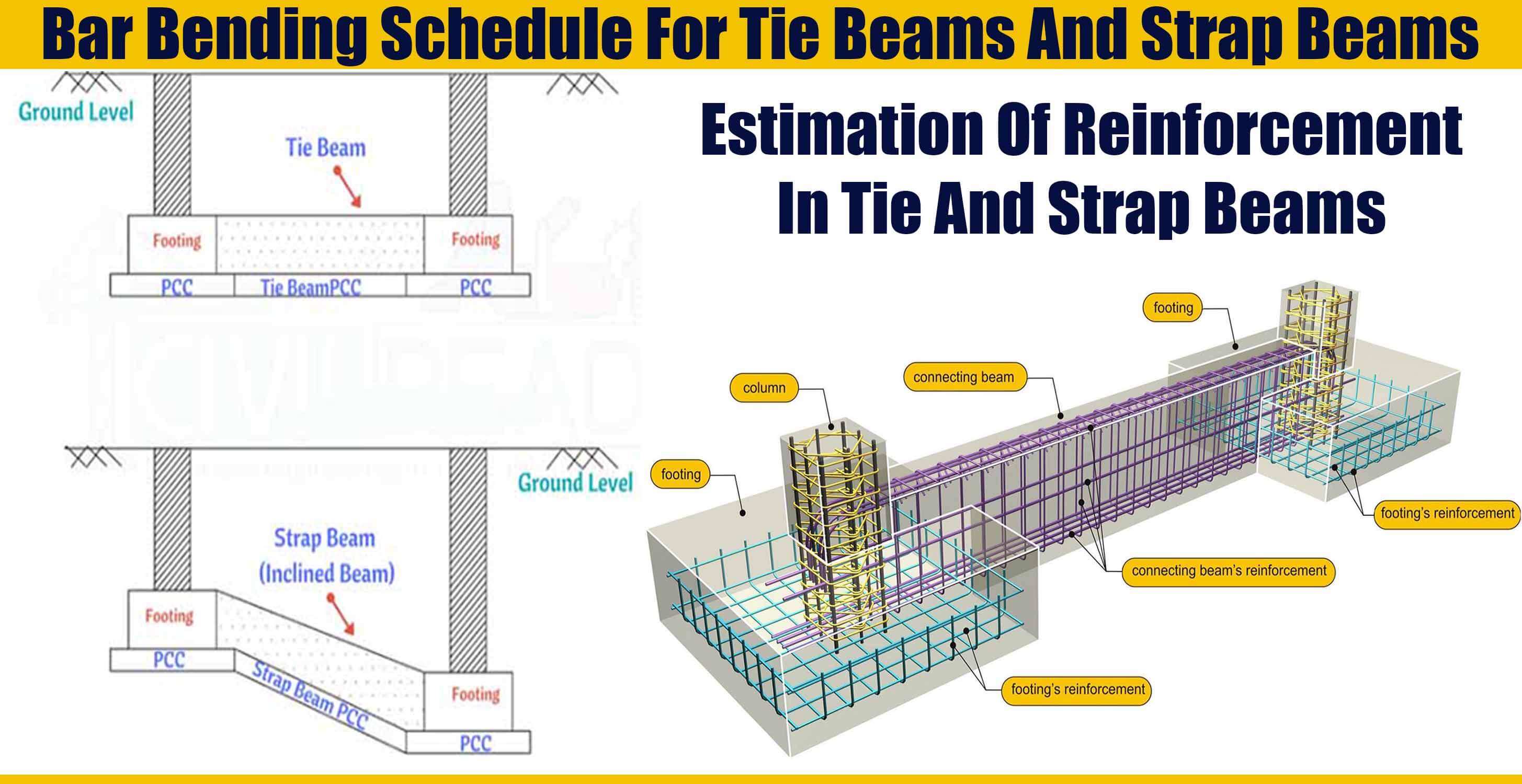
Bar Bending Schedule For Tie Beams And Strap Beams Engineering
A tie beam, also known as an anchor beam, is a horizontal structural component used to resist the lateral forces exerted on a building. It is typically located at the top of a wall or between two columns and acts as a tension member to prevent the wall or columns from buckling or bending outwards.

What Is A Difference Between A Tie Beam And A Plinth Beam? Daily
Get One Month FREE at LinkedIn Learninghttps://bit.ly/2Zq5t95Full Learn To Read Structural Drawing Course at the cheapest rate:http://bit.ly/2Xw0dkvThe tie b.
What Is Tie Beam Tie Beam Details Advantages of Using Tie Beam
A tie beam is a type of beam, which is designed to connect two footings in a substructure. The shuttering alignment of the tie beam should be accurate. Advantage of Tie Beam The tie beam helps the spread footing to maintain its position during external factors such as seismic events, cyclones.
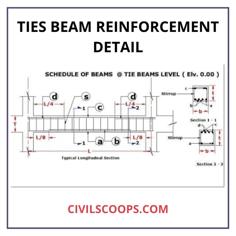
What Is Tie Beam Tie Beam Details Tie Beam Reinforcement
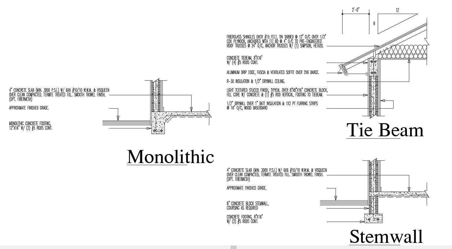
R804.3 Roof Construction. Cold-formed steel roof systems constructed in accordance with the provisions of this section shall consist of both ceiling joists and rafters in accordance with Figure R804.3 and fastened in accordance with Table R804.3. For SI: 1 inch = 25.4 mm, 1 foot = 304.8 mm, 1 mil = 0.0254 mm.
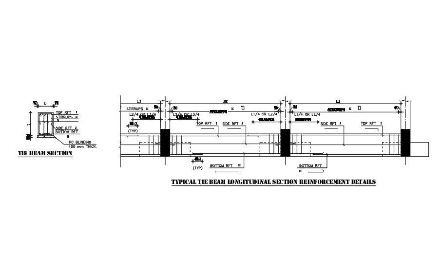
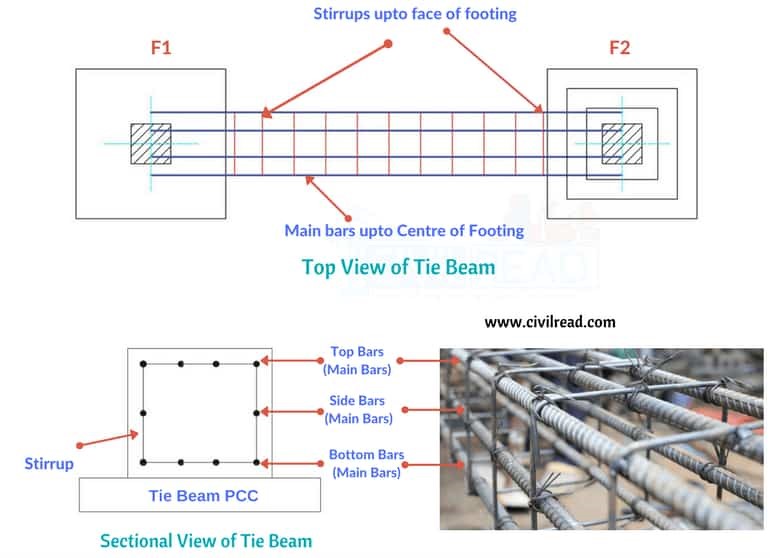
Typical tie beam longitudinal section reinforcement details. Cadbull
Tie-beam is a beam member constructed at a height higher than the floor level to tie or connect two column members or rafters. What are the major differences between plinth beam and tie-beam? Plinth beams are a type of tie-beam constructed at the plinth level. But, both types differ based on the function they perform in a building. Read More
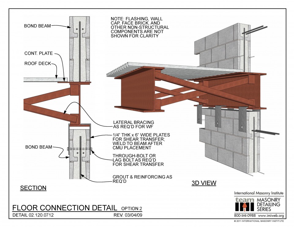
Wall tie Archives Page 2 of 3 International Masonry Institute
A tie beam is an element that ties the posts together. This usually means that there is only one beam in a two-post beam house. The tie beam transfers the load from one post to the next. A plinth beam is a type of beam that is located at the bottom of a column. The most significant difference between a tie beam and a plinth beam is that the tie.

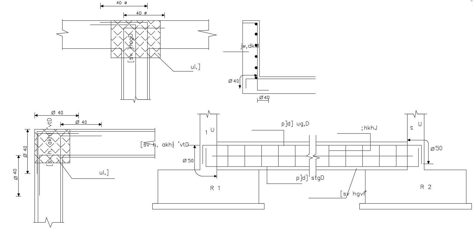
TIE BEAM AND FOOTING REINFORCEMENT SECTION CIVIL ENGINEERING YouTube
Tie Beams is a type of beam used in construction to tie the footing and avoid the slender column effect in the structure. We provide this type of beam when the two footings are in the same line. It connects two or more than two columns and makes a structure as a frame.

Tie Beams Details, Schedule & Reinforcement Of Tie Beams
A tie beam is a critical structural member incorporated in buildings to enhance integrity and stability against lateral loads. Tie beams strongly tie or hold together columns, walls and other vertical members on opposite sides to improve structural performance.
Tie beam details dwg files Cadbull
1. Tie Beam Details When the roof height is more than the usual height of the structure, then these types of beams are kept. They behave as a length breakers in the columns. It joins two or more columns to reduce their effective length and decrease their slenderness ratio. 2. Bar Bending Schedule for Tie Beams

Tie Beams Details, Schedule & Reinforcement Of Tie Beams
Category Drawings. Tags acad Autocad drawing dwg. ClipConnTable - Beam And Connections Using Clip Angles Spreadsheet. Steel Stair Design Based on AISC 360-10 Spreadsheet. Join us on Telegram.

Difference Between Primary, Secondary And Tie Beam Engineering
Footing Tie Beam Design Details Tie beams are used in building construction to prevent column or foundation settlement. It contributes to the column's horizontal load. Tie beams should be installed in buildings if the column height exceeds 4-5m. If the column height is less than 4m, no tie beams are required.
Free Download Structure Tie Beam Design AutoCAD File Cadbull
A typical tie beam might have a width of 230 mm to 300 mm and a depth of 300 mm to 450 mm, with variations depending on the spacing of columns and the load considerations. The primary use of tie beams is to reduce the effective length of columns, thus preventing their buckling under compressive forces.
Tie Beam With Foundation Section CAD Drawing DWG File Cadbull
The beams which make the connection between two or more columns or rafters in a roof or truss or at any height above floor level to make the whole structure more firm and stable at the foundation level is known as tie beam. Tie beams are generally provided at roof truss and floor level and a plinth.
What Is Tie Beam? Tie Beam Details Ties in Column Tie Beam Design
COLUMN TIE BEAM AND FOOTING REINFORCEMENT SECTION DETAILS#CONSTRUCTION#BUILDINGCONSTRUCTION#CONSTRUCTIONCOMPANIES#GREENBUILDING⬤ https://vidiq.com/vidref v.
