
How To Wire 5 Pin Lighted Rocker Switch / 5 Pin Rocker Switch Wiring
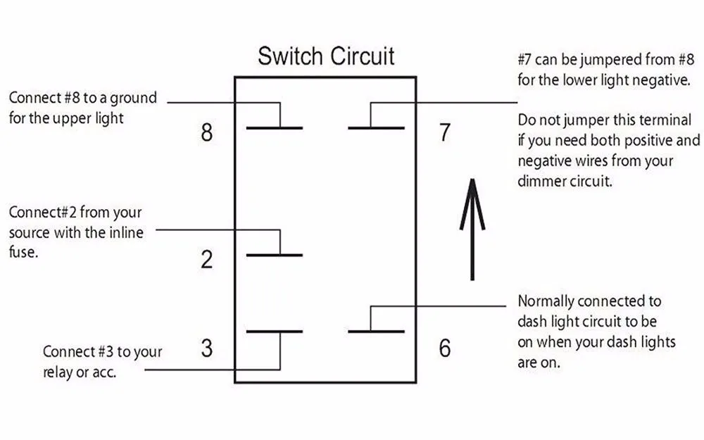
#2 - Power (+) #3 - Outgoing (To Relay, Equipment or Accessory) #8 - Top LED "ON" Light Negative (-) #7 - Lower "Dash" LED Light Negative (-) #6 - Lower "Dash" LED.
Tech Aid 5 Pin Lighted Rocker Switch Wiring Diagram
Last Updated: August 26, 2022 5 min read Contents At a glance, you may think that wiring a 5-pin rocker switch is difficult. Well don't worry, you can do it quickly and easily. Working with car wiring I have installed 5-pin switches in many cars without issues and today I'm going to help you do that as well.

Nilight 5 Pin Rocker Switch Wiring Diagram
https://www.patreon.com/RedneckGaragehttps://twitter.com/RedneckGarage18https://www.instagram.com/redneckgara.https://www.facebook.com/Youtube-videos-43315.
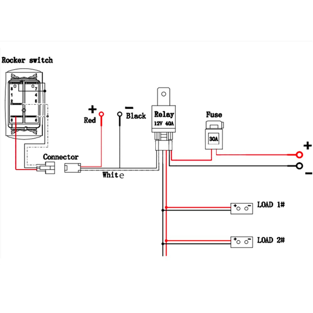
Multiple 5 Pin Rocker Switch Wiring Diagram
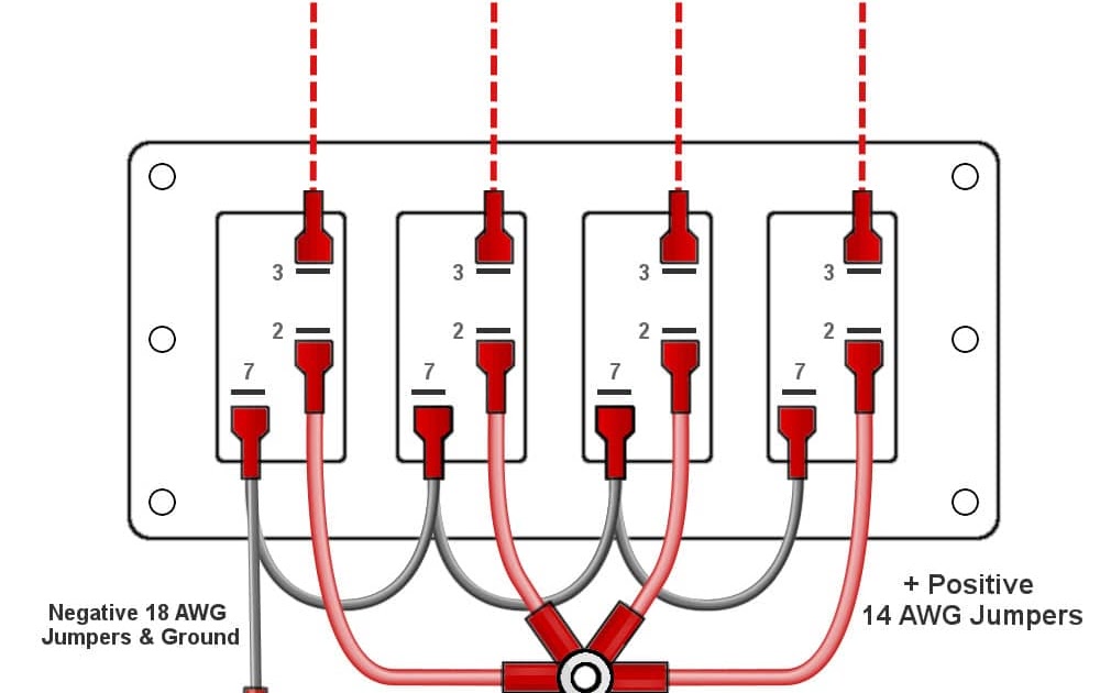
How to make a light bar jumper cable. You will need to make two jumper cables: Ground jumper cables - These will become ground for the ground wire of upper light #8 and ground wire for lower light #7. Positive jumper cable - this will be used for #2 input power, and #6 power is for lower lights. Once that's done, run the rest of the light bar.

Rocker Switches Carling Type
I had nothing to do so I made this quick how to video. In this video I show you how to wire a dual LED rocker switch. The dual LED allows you to illuminate p.
Quality Assurance Momentary Carling Lighted 5 Terminals 5 Pin Rocker
To wire a 3 pin switch to a 5 Pin rocker switch you need to find out what your 3 wires do. Aurora wiring harnesses are set-up as black = ground/negative, red = positive, blue = power to lighting product.

Nilight 5 Pin Rocker Switch Wiring Diagram Esquilo.io
Video | PistonShack Rocker Switches: You'll find these handy little devices in various styles and sizes, so choose one that fits your specific project needs. Video | ChrisFix Electrical Wire: The gauge or thickness of the wire depends on the electrical load of your device. Note: A 14-gauge wire should do just fine for most household applications.

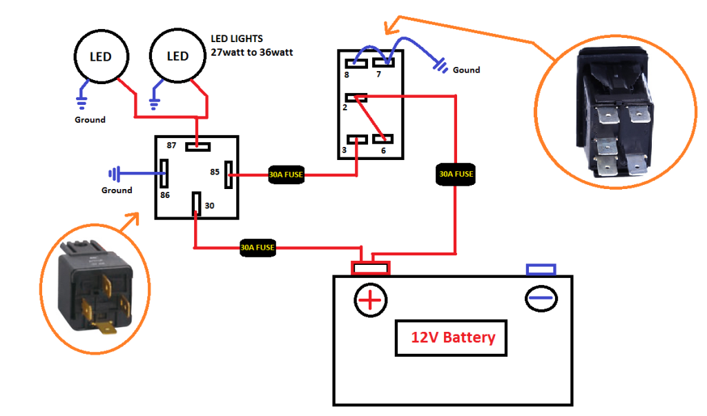
5 Pin Rocker Switch With Relay Wiring Diagram
Rocker Switch Wiring Diagrams As a resource for our customers, we provide below a collection of explanations, wiring diagrams, how to videos, etc of some of the most common Carling rocker switches that we sell. Additional switch specific information can also be found on the product pages for each part. 1. V1D1-B60B - SPST, ON-OFF, 1 Dep Lamp - Top
How To Wire 5 Pin Lighted Rocker Switch 14 Brilliant Wiring A, Switch
The diagram below represents the schematic diagram for a SPST rocker switch: Pin 1 is where the rocker switch receives the input power. Pin 2 is where the accessory that the switch is going to turn on is connected. Pin 3 is where the switch is either connected to ground or left open. Below is a pictorial representation of the schematic diagram:

lighted 8 pin rocker switch wiring diagram Lace Hub
The 5-pin rocker switch, often depicted in a wiring diagram, is an innovative device used to manage an electrical circuit. Each pin or terminal has a specific role; typically, one is for input, two are for outputs, and another is connected via a ground wire to prevent short circuits.

Keystone Epi2 Electric Actuator Wiring Diagram Free Wiring Diagram
First, you need to determine the amp rating of the switch. This rating indicates the maximum amount of current that the switch can handle without overheating or malfunctioning. It is essential to choose a switch with an amp rating that matches or exceeds the needs of your application.
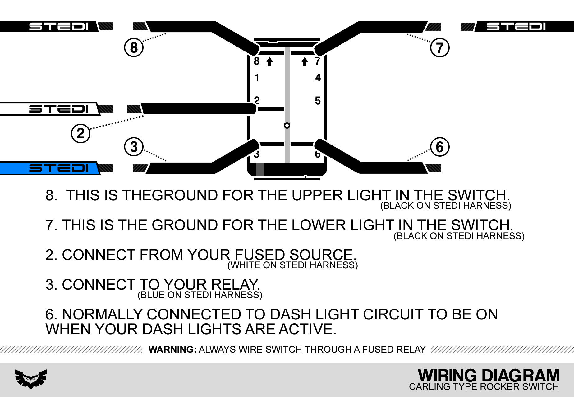
STEDI CARLING TYPE ROCKER SWITCHES AutoElecOz
STANDARD SWITCH WIRING DIAGRAMS Carling Technologies Inc. 611, 621, 610, 620, TA, TILA, 2FA, 6FA, 2GA, 6GA, CA, DA Series RA & RSCA Series 611, 621, 610, 620, TGC, TIGK. 5 E 3 6 LOAD 2 STANDARD SWITCH WIRING DIAGRAMS Carling Technologies Inc. Contact Terminal will make contact with switching lever.
12v Lighted Switch Wiring Diagram Wiring Diagram and Schematic
Illuminated 5 Pin Rocker Switch Wiring Diagram . For an illuminated 5-pin rocker switch, connect two central pins to the power source and device. Connect one outer pin to the ground and another to the device's ground. The fifth pin powers the switch's illumination, typically through a separate 12V source or the device's accessory power..
Dart Wiring 5 Prong Rocker Switch Wiring Diagram
How to Wire a Rocker Switch & Relay - Simple & Easy I explain how I wire a 5 pin rocker switch and a 4 connector relay. I go into detail on the function of each connection. At the.

Mictuning 5 Pin Rocker Switch Wiring Diagram Wiring Diagram
The Nilight 5-pin rocker switch wiring diagram will tell you which pins to connect to which terminals on the switch. It also shows you how to connect the LED lights to the output pin on the switch. This way, you can be sure that the LED lights will be connected properly and safely. Additionally, the diagram will indicate the correct polarity of.
Dart Wiring 5 Prong Rocker Switch Wiring Diagram
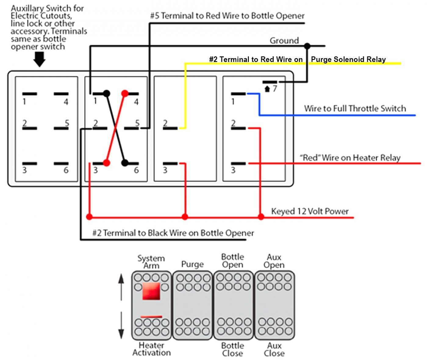
7 PIN ROCKER SWITCH On-Off-On, (On)-Off- (On) & On-Off- (On) DPDT Dual LED Units MORE INFORMATION FOUND ON THE ROCKER SWITCH PRODUCT PAGE 3 PIN DUAL VOLT DISPLAY - ROCKER SWITCH 3 PIN ULTRA MINI ROCKER SWITCH 3 PIN MINI OVAL ROCKER SWITCH 5 PIN UNIVERSAL WINDOW SWITCH
